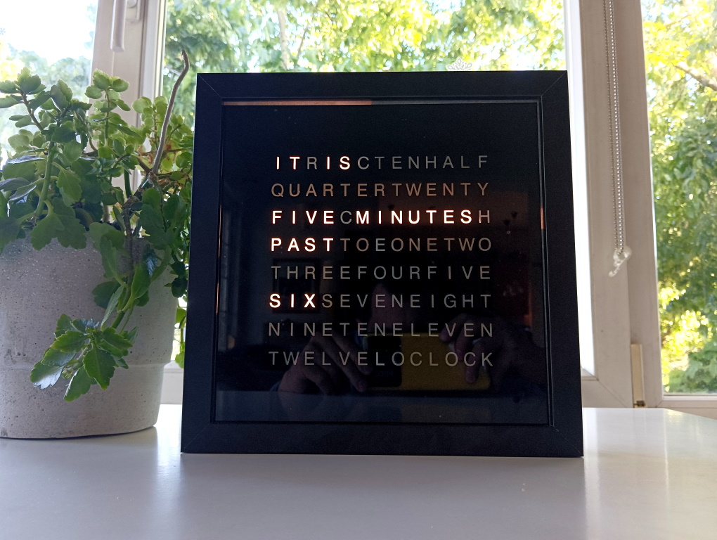
Apparently this project has become a bit of classic in the DIY electronics world, so I decided to give it a go too. If you never seen this before, this clock displays the time using text instead of numbers, in 5 minute increments, but still with minute precision with the 4 extra LEDs that were later added on the bottom.
Credits: Based on Raksith’s version, which in turn is a simplified version of Doug’s.
BTW: Doug also sells complete kits here.
Bill of Materials
- about half a meter of 60 LED/m LED strip, white color
- about half a meter of 120 LED/m LED strip, white color
- Arduino Nano / clone or bare ATMEGA328P micro
- SN74HC595 shift register (x3)
- ULN2803A “LED driver” (x3)
- 2 PCB tactile switches
- real time clock (RTC) based on DS1307 chip
- 12V to 5V step down transformer
- IKEA RIBBA or SANNAHED picture frame
- 12V adapter, 1A minimum
- a piece of baking paper the size of the glass to act as difuser
Apart the materials you will of course also need a frame, the faceplate described below, basic sodlering skills and knowing how to burn a program to an Arduino.
Faceplate
This is probably the hardest non-electronic part to get “right” and there are many variations to it. Personally I went to a local store that makes inscriptions/stamps/prints etc and explained what I wanted. What we need is a material (black in color) capable of blocking light and that can also leave the letters either transparent or cut them out of whatever material was most appropriate.
We ended up carving out letters on a vinyl sticker material with a special printer. The whole sticker was mirrored so that the sticky part became glued to the back of the glass. After squeezing out a few air bubbles here and there the faceplate was ready.
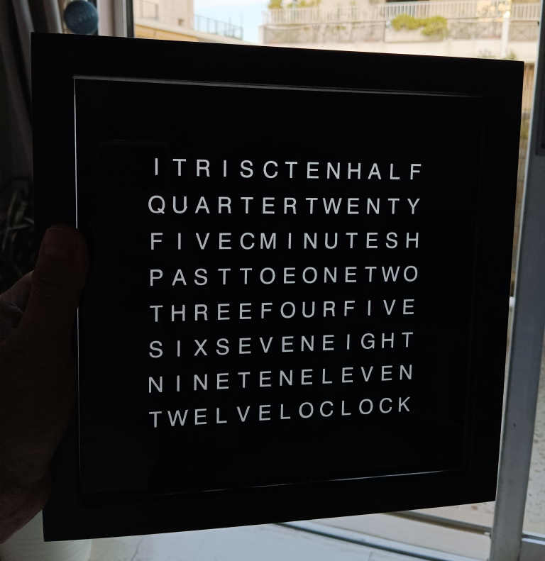
Below is the PDF file used to generated the faceplate. As mentioned, the mirrored version was used by me, but depending on the technology that is available to you the normal version is also available below. The PDF is “true size” with each side being 8.5 inches (or 21.6 cm).
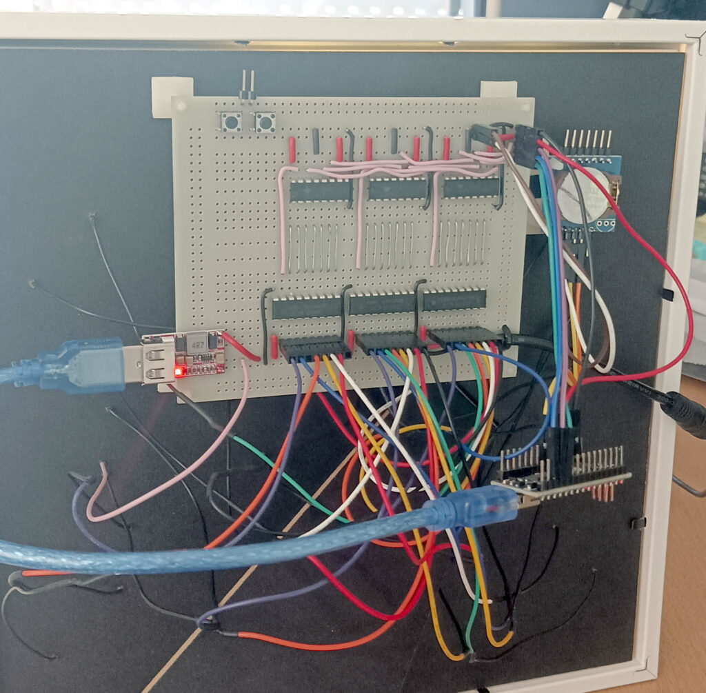
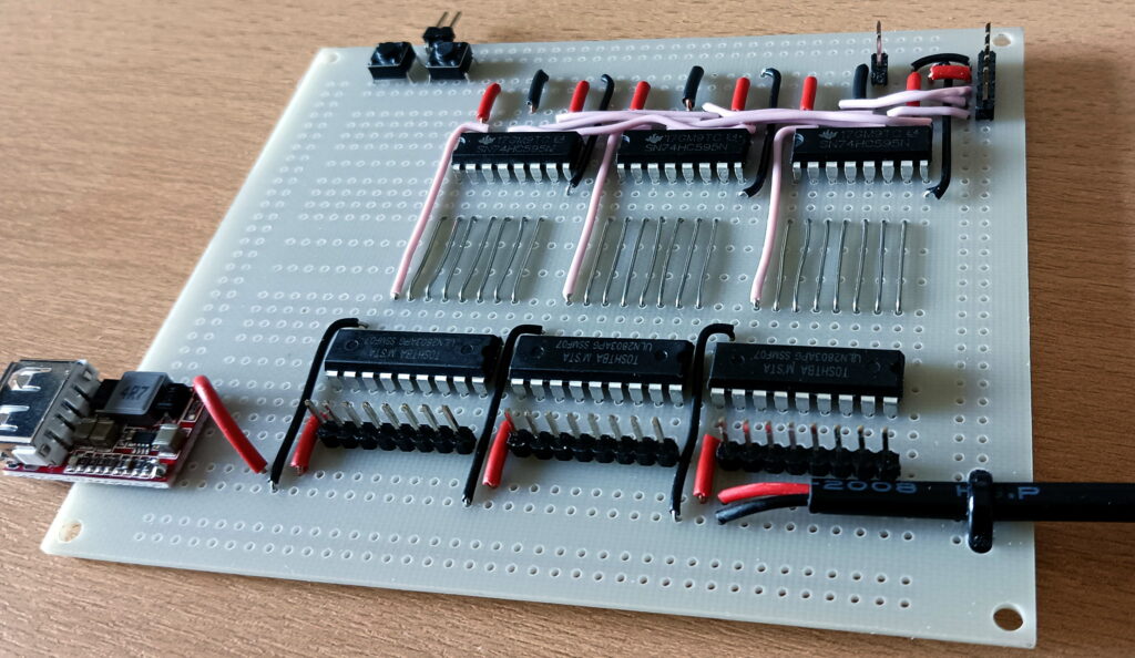
Electronics assembly
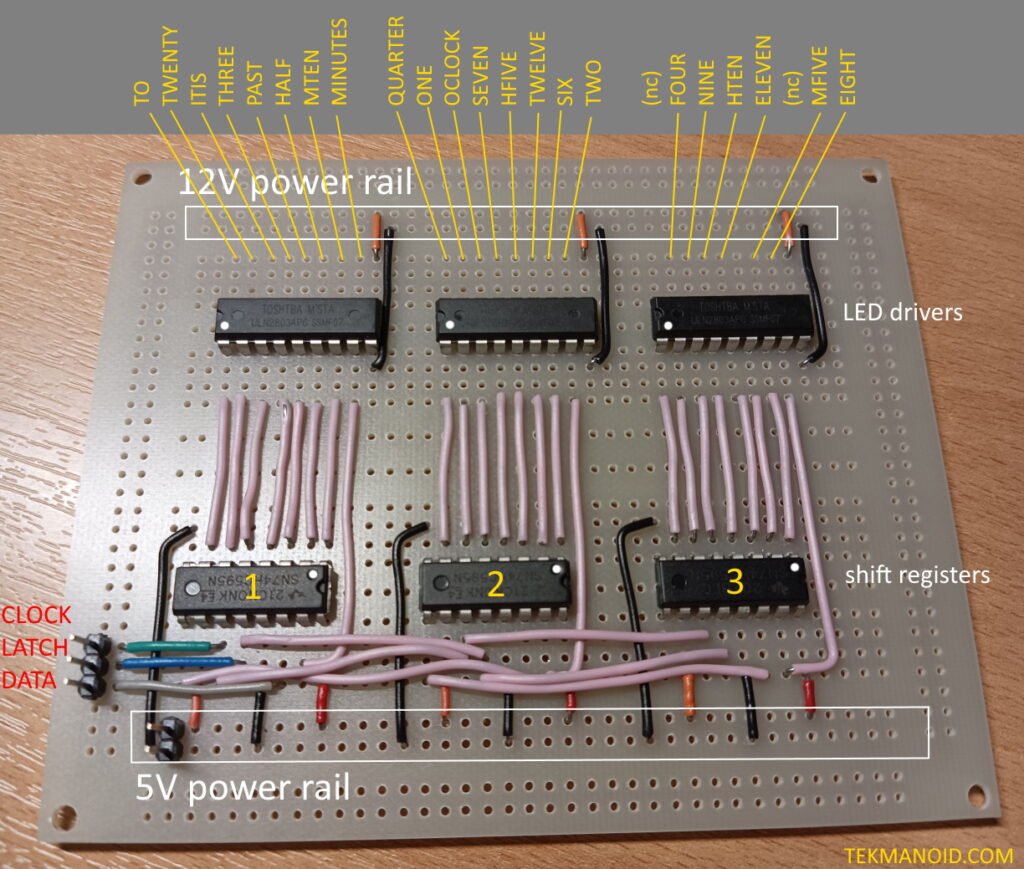
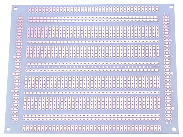
To simplify things as much as possible I used a prototyping PCB specially made for DIP (dual in-line package) chips.
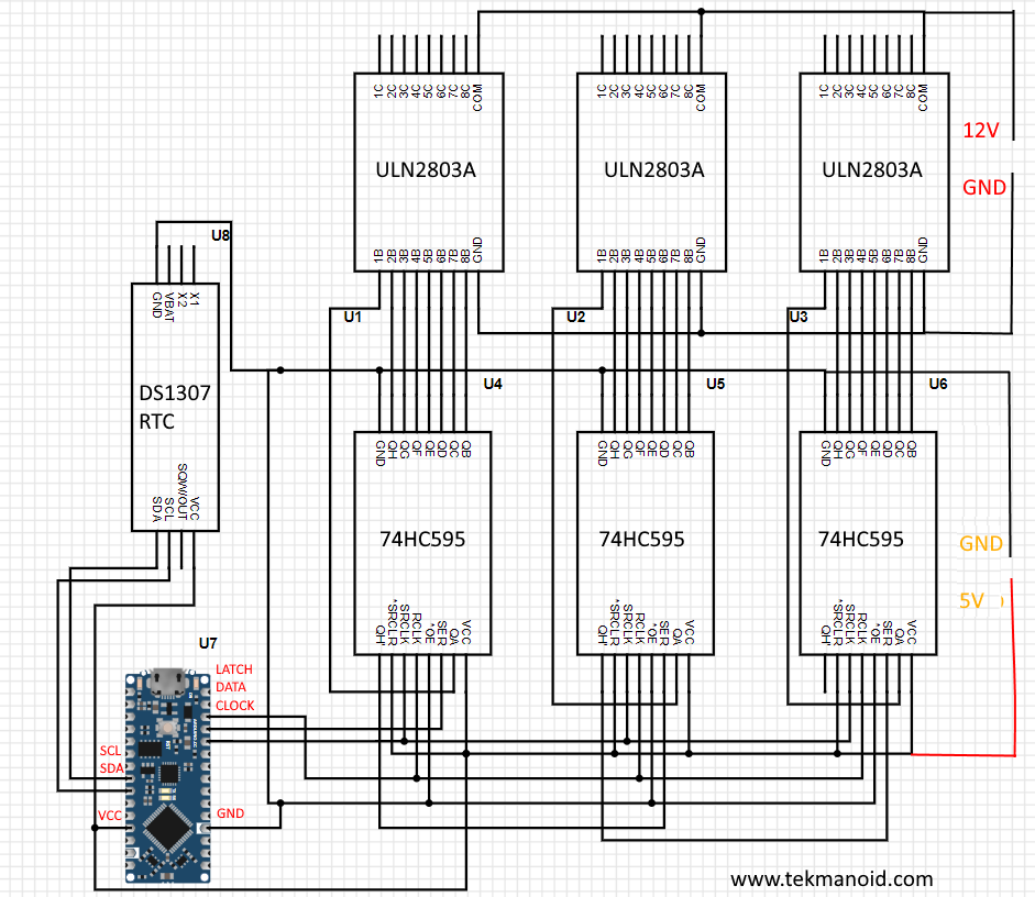
Schematic
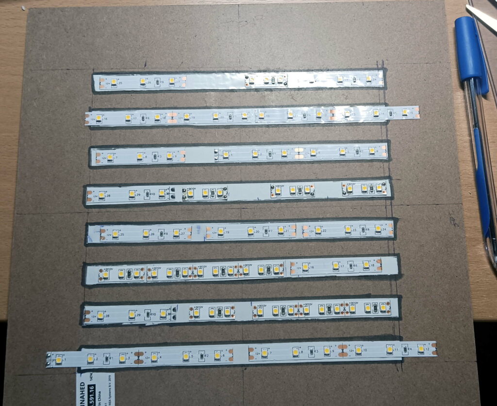
LED strips
LED strips normally allow you to cut every 3 LEDs. The words making up the clock vary in length, and so should the LED segments hiding behind the vinyl faceplate. The reason for using varying density strips is to allow us to accomodate with ease both long and short “words”. For example…with 60 LED/m density the smallest cut is 5 cm long where as with twice the density just 2.5 cm is enough. For the smallest words making up the faceplate, like the word “TO”, only this smaller chunks can be placed in the back. So pick and chose whatever suits you best, in case you printed your own faceplate in a different language than the one proposed here.
Since the absolute maximum current an Arduino pin can source is around 40mA, and even that for short periods of time…we need something to interface the “logic” pins to what will actually “drive” the LED strips.
When driving common anode LEDs, it is necessary to tie the cathodes to a current sink. The ULN chips are high current darlington chips that do this. Current sinking chips such as these are for more common and less expensive than their sourcing counterparts.
Each “driver” inside the chip can sink a maximum of 500mA.
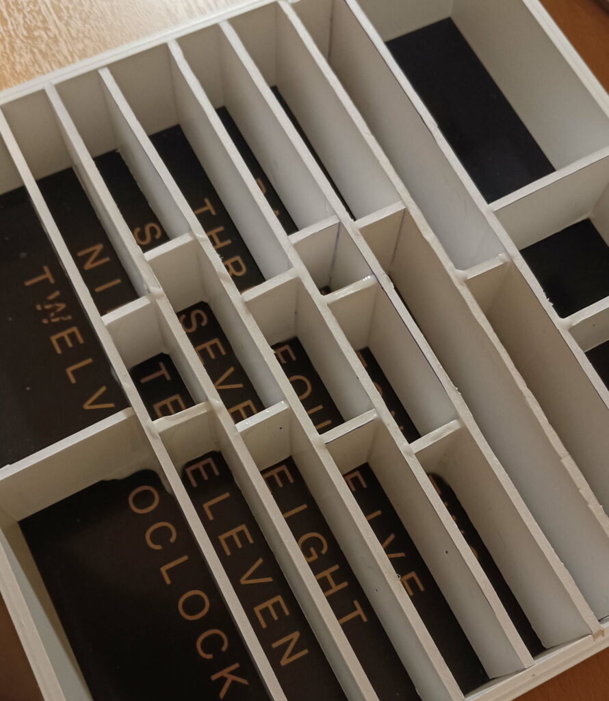
LED strip divisors
We need to make a structure internal to the frame, that will sit between the faceplate and LEDs in order to block the light from flooding into neighbouring words. You can use any light blocking material that you can work with…I went with a special kind of cardboard used by architects to make scale models. Its super light, can be cut to extreme precision and is easy to glue.
Software
The code contains a self test phase that is triggered every time the clock is powered up for the first time. It cycles through all the LEDs, this is especially useful to verify that all LEDs are responding properly.
As with any Arduino code, there is a setup portion that configures the input-output pins. Outputs for driving the shift register chips and inputs for the switches. The I2C protocol and RTC routines are initialized.
In the “loop” section of the code, the current time is fetched from the RTC and displayed every time the second marker hits 0. Within the loop any input from the two “time adjust” switches is also checked.
Setting time
The time is adjusted with two mini switches. One increments the hour and the other increments the minutes.
Power
A 12V adapter able to deliver 2A should cover all setups. During the startup sequence the code will flash ALL LEDS a couple of times. This will test two things…first that the connections have been made properly and that all LED strips are connected to the pins (not necesserily the right ones though). It will also test the adapters capability to drive ALL LED strips.
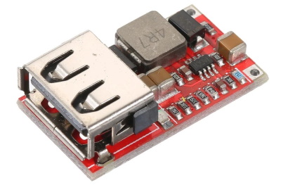
Since Raksith’s design seems to use two power sources which is way incovenient, I opted to step down the 12V of the strips to 5V for the electronics. I happened to find a module that takes anything between 6V-24V and brings it down to 5V through a convenient USB port ready to hook up to the Nano board.
Hope this was helpful and you have fun building your own!