The RDS function used mostly in car stereos has been around for years to convey information digitally alongside with the broadcast. Information such as the name of the broadcasting station, the program, or current song, are only a few things that can be broadcast with RDS.
The RDS project described below, explains how I built a “homemade” RDS decoder in two different flavours: pc-based and microcontroller based. Credit goes naturally to Andreas Nilsson for writing the the microcontroller code. And on the pc based section (Approach 1), I should thank www.esslinger.de for having their software freely available on their website. Hope you get inspired and give it a try too!
The RDS stream is found 57 kHz above the carrier wave, together with the multiplexed stereo signal and the mono signal. One of RDS decoder IC’s tasks is to filter out this incoming signal found around 57 kHz. The question one would ask himself is “So, where do I find this multiplexed signal, in a given radio receiver?”. One location is at the input of FM-stereo demux chip, (FM decoder). “So how do I find the FM-demux chip?”. Well…there are many manufacturers that make such chips, and sometimes even two identical chips can have different chip-numbers. I started by opening the radio and examining the radio section and noted down all the chip numbers that I could find. The radio is manufactured by Hitachi, so almost all the chips were their own (HA). It is very likely that you will find the same chips in other brands too. This is what I got: HA11226, HA11227, HA12413 etc… Then I used search engines on the internet to get a description of the chips from these chip-numbers. This is what some of the chips turned out to be:
HA11226 Dolby Noise Reduction
HA11227 FM Stereo MPX Decoder
The MPX Decoder chip is the one we are going to use! The next step is to try to locate the input pin on this chip. For this, there is nothing better than the chip manufacturer’s product sheet, found just about always in PDF format. I tried searching in Google, with no luck. After a while I found a product sheet of an equivalent chip, which means that the only thing that differs from my chip is the chip-number. According to the product sheet the input pin (MPX IN) is pin number 2. Another pin you will need is the “ground” (GND) found just about anywhere in the radio. But I chose to solder my cable on pin number 7. These two cables were then made available outside of the radio through a small hole. You may also chose to incorporate the whole decoder inside the radio, if there is enough space.
RDS Decoder Chips
To make RDS decoding fit on a project board, you need some help with the most difficult part, namely: the actual isolation of the RDS data stream from the radio. Thanks to Philips and SGS-Thompson, there are two chips that do the job!
- SAA6579 – Philips
- TDA7330 – SGS-Thompson
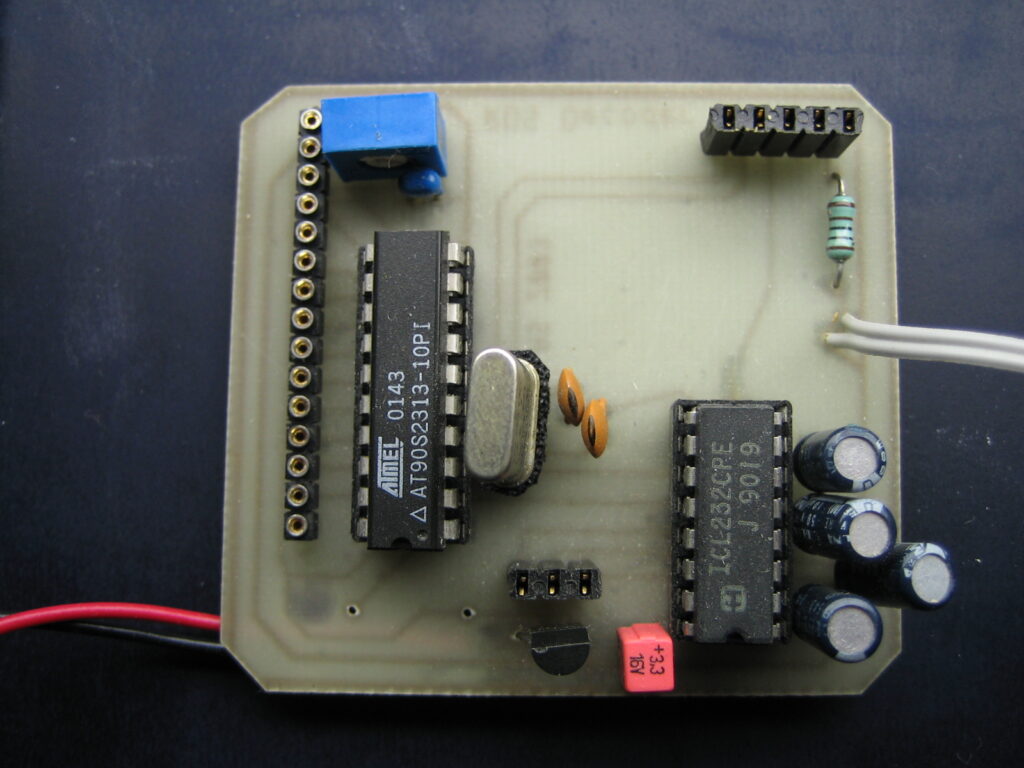
The two chips above are the most common. Personally I use the one from Philips. I will admit that the chips can be hard to get hold of. They cost roughly €5 each. These chips are basically the same in the sense that they receive a multiplexed signal as an input, process the RDS stream, and give the RDS DATA and RDS CLOCK as outputs on two pins. This is raw data. It still needs some manipulation to make any use of it. From a techies point of view this is were the actual decoding will take place. The RDS protocol will have to be studied, and from there write a program (easier) or build hardware (harder) that decodes the information from this raw data stream into an understandable form. The decoder chip just needs a few external components to work. I decided to use SMD components on a small PCB (see below) and have a small RDS decoder unit which is easily transferable between projects.
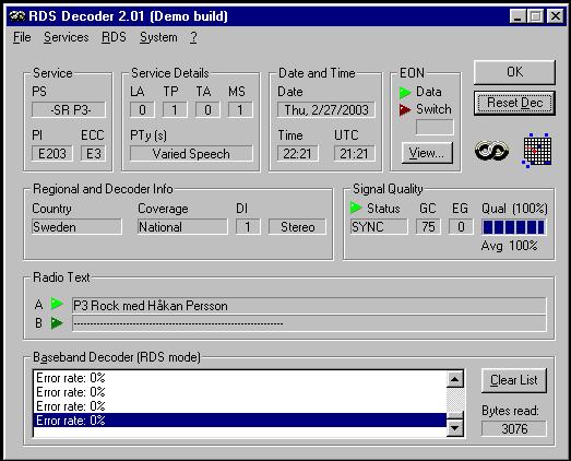
Approach 1 – PC based Decoder
If you want to make RDS decoding as simple as it gets, this is the approach for you. There is a windows based RDS decoding program out there provided by Esslinger. If you read the documentation of the program you will see that all you need to do, is connect the RDS DATA and RDS CLOCK pins through a simple interface to the PC’s COM port. The actual decoding will be done in software on the PC side. This is described in detail in the software documentation. Instead of the classic MAX232 voltage converter they advise you to use a cheaper TTL IC, the 74LS14. So…time to connect our device to the computers COM port and start the RDS decoding program by Esslinger.
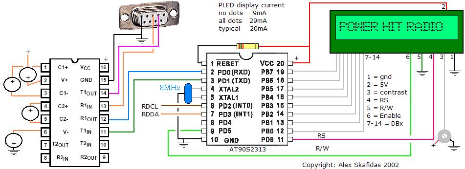
Approach 2 – MicroController based Decoder
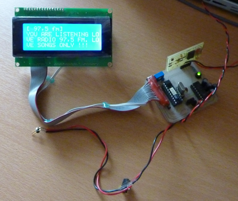
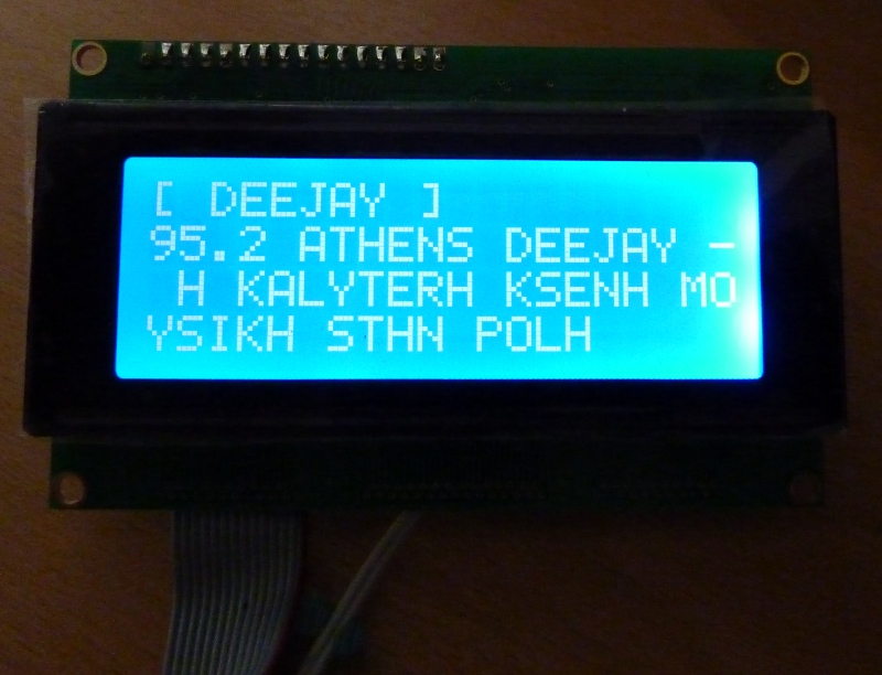
The processing of raw RDS data in this approach will be handled by the Atmel’s AT90S2313 microcontroller which is the “heart” of this project. The source code that does this processing was written by Andreas Nilsson. For copyright reasons only the machine code (HEX) file is made available used to program the device. The file will work for the above setup and display RDS info on a 4×20 line LCD. It will display PS (Program Service Name) on the top line and RT (Radio Text) on the remaining 3 lines. A 2×16 display could also be used, but then most of the RT will not be visible (if used at all by the radio station).
File Resources
<TODO>