If you own a scanner then you have certainly heard those annoying quick sound sequences used by various law enforcement agencies etc. These sound sequences are generally called SelCall (Selective Calling) and is a form of paging for activating only those radios of interest. When a radio detects the sound sequence which it has been programmed for, it will be activated and let the audio through. The are about 5, 6 standards for selcall paging. The most common are probably ZVEI and CCIR.
There are two paths to follow for decoding these sequences,
- the use of a dedicated selcall chip and microcontroller, or
- doing everything with a microcontroller.
1a. PIC microcontroller & CMX823
SCHEMATIC & HEX (written by K3SVW Max) The decoder below uses a dedicated chip: CMX823 for selcall decoding made by CML. Besides decoding 5 to 6 formats it can also be programmed to decode a proprietary set of sequences. In combination with the microcontroller The gadget below can be used to decode / display these sound sequences and give the option to trigger a relay, light up a LED etc…

1b. ATMEL microcontroller & CMX823
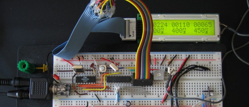
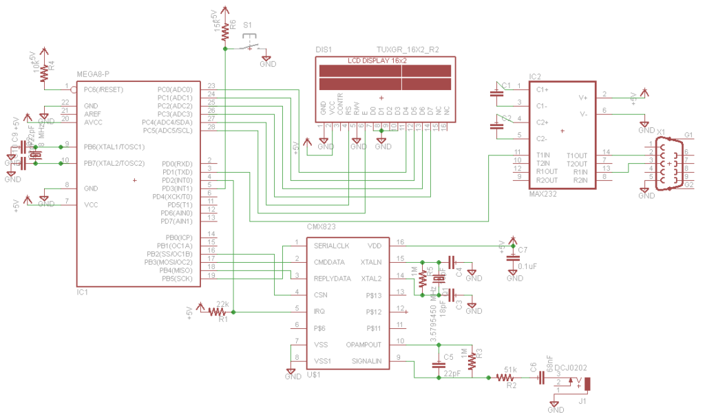
Using the same hardware I decided to reproduce Max’s project but using an ATMEL microcontroller instead of Microchip’s PIC. Another difference is that the PIC version was written in Assembler, while my code was written in C using the free AVR-GCC compiler. Results were very good. By the press of a button, the user can select among 3 paging formats (CCIR/ZVEI/EAA). When a format is selected the tones are programmed in the CMX823 volatile memory one by one. The micro then immediately enters an endless loop. The only thing that can interrupt this loop is an incoming interrupt from the CMX823 peripheral chip. An interrupt is fired any time the incoming tone matches one of the programmed tones during startup. The interrupt is fired for a matching tone regardless of its duration (ms). It is the task of the micro to evaluate the received information and decide whether to display it on the LCD as a valid decode. To help evaluate the tone sequence the micro’s TIMER function came in handy. Upon an interrupt the time difference between the current and the previous tone are stored in a separate array. If the tone durations vary too much among each other then the micro assumes that voice was mistakenly perceived as a tone sequence and is therefore discarded. Below is the schematic of the AVR based Selcall decoder.
Partlist
- 1 ATMEGA8
- 1 CMX823
- 1 8 MHz crystal
- 1 push button switch
- 1 2×16 char LCD
- 1 MAX232
- 1 female COM port
- 1 3.579545 MHz crystal
- 1 3.5mm audio connector
- 1 10k res.
- 1 22k res.
- 2 1M res.
- 1 56k res.
- 1 15k res.
- 1 0.1 uF cap.
- 5 22 pF cap.
- 1 68 nF cap.
Schematic

2. Microcontroller only
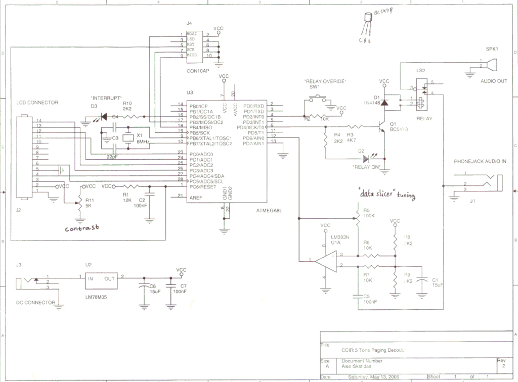
This second option is surely more educative from a programming point of view. Here a microcontroller is used both for detecting the audio sequence and for displaying it on an LCD. The incoming audio is fed through a “data slicer” made with an LM393 OP-amplifier. The output basically detects zero-crossings and a square wave is fed to the microcontroller via an interrupt pin. Everytime the pin goes from high to low it will trigger an interrupt. The microcontroller will measure the period between the interrupts and use that to determine the frequency of the incoming audio. if this frequency is detected long enough (around 50 ms) and it falls within the range of a valid tone frequency, then it will be stored in a temporary variable. If at least 4 tones are received within 500 ms of the first tone detected then the whole received sequence will be displayed. The code was initially written in BASIC using BASCOM compiler with the ATMEGA8L chip for decoding ZVEI sequences. Since the timing and selcall format will most likely need to be changed to suit every need, the source code will have to be modified and recompiled.
Schematic

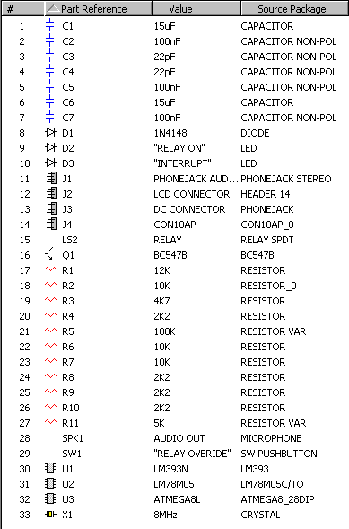
Partlist

File Resources
<TODO>